
Various injection molding gate types influence the quality of the plastic mold. These gates are of different sizes and dimensions and can determine the design of the molded plastic product. Here are some of them:
1. Direct or Sprue Gates
The direct/sprue gate type is simple and common in injection molding. The sprue moves and melts directly into the mold cavity allowing the quick injection of large plastic volumes. It usually requires less injection pressure and a short feeding time. Direct gates are easy to design and offer high tensile stress around the gate.
The simplicity of this gate design makes it suitable as an economical option. However, these gates may create marks on the finished parts as the sprue gate must be removed manually from the injection molded parts by the technician.
The direct gate is primarily suitable for shell or boxed molds with deep single-cavity and non-aesthetic parts. It is common in house appliances and consumer products like washing machines, bins, TV, printers, etc.
2. Edge Gates
The edge gate is the most popular and straightforward injection mold gate design. As the name implies, it is usually positioned along the edge of the workpiece, forming a visible mark at the demarcating line. It has larger cross-sectional regions that allow sufficient molten plastic flow into the cavity.
The edge gate is relatively cheap to design and ideal for flat parts and medium or thick sections. Edge gates do not require a specific resin wither type, making them an ideal choice if you can simplify your design for injection molding.
3. Submarine Gates
The submarine or tunnel injection molding gate is usually placed below the mold parting line, facilitating automatic trimming during component ejection. It involves using a narrow channel that joins the cavity near the parting line, filling the cavity from below the parting line. Likewise, the draft angle facilitates easy ejection of finished plastic parts without breaking.
This high-shear gate allows little molten plastic into the mold cavity. As a result, the submarine/tunnel gates are ideal for molding small components. Using them for larger parts will lead to unnecessarily long cycle periods and poor surface finishes caused by shear heating.
4. Cashew Gates
The cashew gate has the shape of a tree nut. Manufacturers use this gate type for products that can be disfigured during gate removal. The cashew gate has a curved structure, making it challenging to extract molded parts without damaging or deforming them.
Cashew gates can reach other challenging areas of the mold that cannot be joined or linked by the regular tunnel gate. As a result, injection molding manufacturers install removable fittings that are easily detached during the ejection process.
This gate type is not limited or best fit for any particular plastic resin. Hence, the options remain open if you consider this gate type based on the needs of your product designs.
5. Diaphragm Gates
The diaphragm gate and the sprue gate are somehow identical in appearance because they both taper off from underneath the gate. These gates are generally used with molded parts with angular shapes. The diaphragm gate effectively reduces the formation of weld lines and wrapped shapes on the molded parts, even though the injection molding process’s temperature, speed, and pressure can influence the quality of the ejected part.
Diaphragm gates are suitable for larger parts that need a significant amount of resin to complete the molding process and fill out the part. The diaphragm gate design is compatible with most resin types and is an ideal option based on the product’s design.
6. Hot Runner Valve Gates
The essence of the hot runner mold system is to retain the molten plastic in its liquid position till it fills the mold evenly. There is a certain pressure and temperature setting that helps to achieve this. The hot runner valve gates maintain the same pressure and temperature conditions as the runners. Likewise, the valve gates keep the exact width dimensions as the runners.
The hot runner valve gate has ejector pins, giving it control advantages. The molten plastic flows into the gate when you pull out the pin, and the flow stops when you push the pin back in.
Furthermore, pushing the pin back to its position forces any plastic left in the gate into the mold. It prevents the building up of material in the gate, thereby improving efficiency. The hot runner valve gate offers a more reliable control mechanism in the injection process, simultaneously allowing individual control of multiple gates.
7. Hot Runner Thermal Gates
The hot runner thermal gates have a set temperature and pressure like the hot runner valve gates. The thermal gate is only used in a hot runner system and placed at the top of the parts just above the mold parting line. This injection molding gate design does not require the runner’s help before filling the injection mold. This design excludes the need to separate the gate from the finished part after molding.
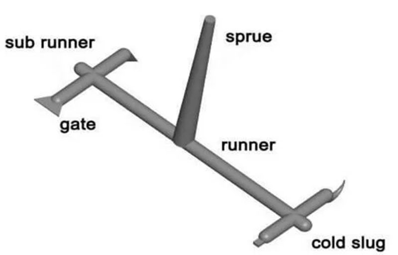
The hot runner thermal gate works differently from other gate designs as it has no pin or valve functioning as a shut-off mechanism. The molten plastic flows through it onto the valve. The plastic left in the gate creates a cold slug known as the “thermal gate” once the flow stops acting as the temporary stopper.
As the subsequent flow of molten plastic flow through the gate, it melts and pushes the temporary thermal gate into the mold. It is primarily compatible with various resin types, making it an ideal option for most designs.
8. Fan Gates
Fan gates, as the name implies, are in the form of a fan. These gates allow mold to flow into the cavity through a broad opening. The gate widens gradually to form a fan shape from the runner through to the direction of the mold cavity, maintaining consistent thickness. They are often used to establish a stable flow into large parts.
A fan gate helps to prevent injection molding defects while maintaining dimensional stability in parts. In addition, a fan gate is ideal for making flat and thin products due to its ability to limit directional stress and flow marks. Fan gates are usually suitable for polycarbonate plastics.
9. Pin Gates
Pin gates are usually placed on the B-side of the mold near the ejector pins. A pin gate is ideal for three plate molds with the runner channel located in a different runner plate; the mold flow is split in several directions, leading to the cavity by various gate locations. The gate point is very small, allowing it to be trimmed off by the injection mold opening. It has a high scrap rate due to the large runner, which is a disadvantage.